Leave Your Message
Choosing Stamping Die Parts in 2026 requires more than matching catalog numbers. The right choice affects accuracy, press stability, maintenance time, and the final cost of every production run. A punch, die button, guide post, spring, or retainer must suit the material, thickness, press speed, and expected volume.
Tooling specialist David A. Smith observes, “A die is only as good as the parts that support its working surfaces.” This practical view remains important in modern stamping. High-strength steel may demand tougher tool materials and improved wear resistance. Aluminum may require smoother surfaces and careful clearance control. A small mismatch can create burrs, noise, premature wear, or repeated stoppages.
Details matter most.
This guide will examine how to select Stamping Die Parts for progressive, compound, and single-operation dies. It will compare tool steel, carbide, coatings, tolerances, standardization, and supplier consistency. It will also consider sensor-ready components, quick-change designs, and data-based maintenance planning for 2026 production environments.
However, no selection chart can replace engineering judgment. A “standard” part may still perform poorly under unusual loads or poor lubrication. Even a premium component can fail when installation is careless. That uncomfortable reality deserves attention. Reliable choices come from measured press conditions, clear drawings, trial results, and honest feedback from operators.
The goal is not to buy the most expensive parts. It is to choose dependable components that fit the process, remain serviceable, and protect quality over time.
How to Choose Stamping Die Parts in 2026?
Define Stamping Die Parts and Their Functions
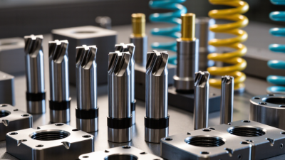
Stamping die parts are the working and supporting components inside a metal-forming tool. They guide, cut, bend, or hold sheet material during each press cycle. A punch pushes metal into or through a die cavity. The die block controls the final shape and cutting edge. A stripper plate removes the formed part from the punch. It also helps prevent material from lifting.
Guide posts and guide bushes keep the upper and lower die sections aligned. Even slight movement can create uneven edges or premature wear. The die shoe supports these components and transfers press force safely. Springs, gas units, or elastomer pads control return movement. Their force must match the material thickness and forming load.
Choosing parts requires more than matching dimensions. Check working clearance, surface hardness, load capacity, and maintenance access. For example, a small clearance may produce cleaner cuts but increase galling risk. A larger clearance may extend tool life, yet leave rough edges. In practical shop testing, I inspect wear marks after several production cycles, not only after assembly. That evidence often changes the original selection.
Material strength also matters. Hardened tool steel suits cutting edges, while wear-resistant inserts can support high-volume areas. Still, stronger is not always better. Brittle parts may crack under impact. I have also seen accurate drawings fail because lubrication, alignment, or press stability was overlooked. Record these conditions before approving the final die design.
| Die Part | Definition | Primary Function | Common Material | Key Selection Factors | Typical Failure Risk |
|---|---|---|---|---|---|
| Punch | The male cutting or forming element that enters the die opening. | Cuts, pierces, bends, draws, or forms the sheet metal. | Tool steel; powder metallurgy steel for demanding production. | Part geometry, sheet thickness, required wear resistance, clearance, and press tonnage. | Chipping, cracking, galling, and premature edge wear. |
| Die Block | The female die section containing the opening or forming cavity. | Supports the workpiece and provides the cutting or forming surface. | Hardened tool steel or carbide inserts for high-wear applications. | Opening geometry, die clearance, material strength, wear life, and ease of maintenance. | Burring, cracking, excessive clearance, and misalignment. |
| Stripper Plate | A plate positioned around the punch to separate material from the punch after the stroke. | Strips the sheet from the punch and may also guide or hold the strip. | Prehardened or hardened tool steel; wear-resistant inserts when needed. | Strip thickness, punch layout, spring force, clearance, and required guiding accuracy. | Material sticking, uneven stripping, plate deflection, and punch damage. |
| Guide Post | A precision cylindrical post fixed to one die shoe. | Aligns the upper and lower die assemblies during closing. | Hardened bearing steel or alloy tool steel. | Die size, stroke length, required alignment accuracy, load, and lubrication conditions. | Bending, scoring, seizure, and loss of die alignment. |
| Guide Bushing | A precision sleeve that receives and guides the corresponding guide post. | Maintains repeatable alignment and reduces lateral movement between die halves. | Hardened steel, bronze, or other bearing-grade materials. | Fit tolerance, bearing length, lubrication method, operating speed, and contamination control. | Wear, excessive clearance, galling, and inaccurate part production. |
| Die Shoe | The upper or lower base plate that supports and locates die components. | Transfers press force and provides structural support for the die set. | Machine steel or cast steel, selected according to die size and load. | Press compatibility, rigidity, weight, mounting pattern, and resistance to deflection. | Deflection, cracking, loose mounting, and permanent deformation. |
| Punch Holder | A component that secures the punch and connects it to the upper die assembly. | Maintains punch position and distributes press force into the punch. | Alloy steel or hardened tool steel in high-load areas. | Punch shank size, mounting method, impact load, rigidity, and replacement access. | Punch loosening, stress concentration, cracking, and poor concentricity. |
| Backing Plate | A hardened plate placed behind a punch, die, or holder to distribute concentrated loads. | Prevents indentation and protects supporting surfaces from high compressive stress. | Hardened tool steel or high-strength alloy steel. | Contact area, press load, hardness, thickness, and flatness. | Indentation, bending, fatigue cracking, and uneven force transfer. |
| Stock Stop | A fixed or adjustable locating element that controls strip or blank position. | Sets feed length and establishes the position of each workpiece. | Hardened tool steel or wear-resistant alloy steel. | Feed pitch, strip width, adjustment range, contact wear, and operator access. | Dimensional variation, impact wear, burr interference, and feeding errors. |
| Pilot | A small precision pin that enters a previously pierced hole before forming or cutting. | Corrects strip position and improves accuracy between successive operations. | Hardened tool steel or carbide for severe wear conditions. | Pilot diameter, hole size, entry chamfer, timing, clearance, and strip stability. | Bending, breakage, hole enlargement, and inaccurate registration. |
| Die Spring | A spring element used to return or apply force to a die component. | Provides stripping, cushioning, return, or clamping force during the press cycle. | Spring steel; material grade depends on force, travel, and cycle life. | Required force, working deflection, fatigue life, operating temperature, and available space. | Fatigue failure, coil set, overheating, and insufficient return force. |